
Friday, 27 April 2018
Thursday, 26 April 2018


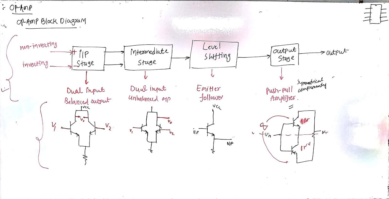
Basic Electronic - Block diagram of Op-Amp
Find lecture note over here
For questions you can ask in comment box

For questions you can ask in comment box
Basic Electronic - Integration & Differentiation lecture note
Here is the board work done in class room..
You can ask questions in comment section

You can ask questions in comment section


Wednesday, 25 April 2018
CRIMPING PROCESS ( RJ 45 Connector )
A crimping tool is a tool designed to crimp or connect a connector to the end of a cable. For example, network cables and phone cables are created using a crimping tool to connect the RJ-45 and RJ-11 connectors to the end of the cable. In the below example picture, this crimper is capable of crimping a RJ-11 (6-Pin) and RJ-45 (8-Pin) connectors and also includes a wire cutter near the handles that can be used to cut phone or CAT5 cable. To use this crimping tool, each wire is first placed into the connector. Once all the wires are in the jack, the connectors with wires are placed into the crimping tool, and the handles are squeezed together. Crimping makes the plastic connector puncture and hold each of the wires, which prevents the wires from falling out and for data to be transmitted from the connector to each of the wires.
TIA/EIA Twisted Pair Categories
CAT3:
ØContains four wire
pairs
ØProvides 10 Mbps
throughput and 16 MHz bandwidth
ØLimits segment length
to 100 m (330 ft)
ØWidely used in VoIP
networks
CAT4:
ØProvides 10 Mbps
throughput and 20 MHz bandwidth
ØCarries better
interference protection than CAT3
Both are replaced by newer UTP categories
Both are replaced by newer UTP categories
CAT5:
ØContains four wire
pairs
ØProvides 100 Mbps
throughput and 100 MHz bandwidth
ØLimits the length of
each segment to 100 m (330 ft)
ØConnects to a NIC via
an RJ-45 connector
ØUses 118 twists per
meter (3 per inch) on average
ØWas produced in large
quantities – still widely available
ØInexpensive,
effective, popular
CAT5e:
ØA version of CAT 5
cable with high-quality copper
ØContains four wire
pairs
ØHas higher twist
ratios
ØIncorporates better
cross-talk reduction methods
ØProvides 350 MHz
bandwidth
ØAllows 350/100 m
segments at 100/1000 Mbps
ØInexpensive – widely
used within 1 Gbps networks
CAT6:
ØContains four wire
pairs, each wrapped in foil insulation
ØAdditional insulation
covers the bundle of four pairs
ØCarries
fire-resistant plastic sheath on the outside
ØResistant to
crosstalk
Ø250 MHz bandwidth
provides up to 10 Gbps throughput
ØAllows 100 m (300 ft)
long or 37 m (120 ft) long segments (for up to 1 Gbps or 10 Gbps,
respectively)
ØUses newer GG-45
connectors
ØWidely used in modern
1 Gbps networks
ØA higher-grade
version of CAT6 cable
ØAllows longer segment
lengths – up to 100 m at 10 Gbps
ØProvides 550 MHz
bandwidth
ØRequires GG-45
connectors
ØDe Facto standard on
modern networks
CAT7:
ØContains increased
amount of shielding
ØLarger, heavier, less
flexible
ØHas 600 MHz bandwidth
ØProvides 10 Gbps
throughput on up to 100 m (330 ft) segment length, with large margin
ØRequires GG-45
connectors
ØDe Facto standard on
modern backbone networks
CAT7a:
ØIn theory – 1 GHz,
40/100 Gbps at up to 50/15 m
ØCurrently under
development


Variable Power Supply ( by PCB layout for Single layer Design )
1.2 ~ 24V @1A, Regulated DC
Power Supply Using LM317
This simple low cost
DC power supply circuit provide very stable DC voltage (adjustable) from
1.2V to 24V. The use of LM317T regulator IC simplifies the circuit by reducing
the number of required external components. The total parts count is less than
10
The maximum output current is 1A
You may use it to power your electronic projects that require stable DC
supply.


FEATURES:
OUTPUT
VOLTAGE RANGE: 1.2 TO 24V
0.1% LINE
AND LOAD REGULATION
Equation for calculation of output voltage:
Vout =1.25 x
( 1+ VR1/(R3+R4) )
where R3
=470Ω, R4= 56Ω & VR1 adjustable from 0 ~ 10KΩ
Eg.:
VR1=0Ω when it's fully counter clockwise,
Output voltage =
1.25x(1+0/(470+56) = 1.25V
VR1=10K Ω when it's fully
clockwise,
Output voltage =
1.25x(1+10,000/(470+56) = 1.25x(1+19) = 25V

PARTS LIST:
IC1: LM317T 3-terminal
adjustable linear voltage regulator IC
LED1 3mm or 5mm LED
(Any Colour)
D1, D2 1N540x (X=2,..., 8) rectifier diodes ( if possible purchase 1N5402)
Resistor: (1/4W
or 1/6W)
R3 470Ω
R4 56Ω
R5 3.3K
Potentiometer: (B) 10K (linear taper) (output voltage adjustment)
Capacitors:
C1 either 2200
uF, 63V (min 35 V)
C2 100 uF
25V (min) Electrolytic capacitor
Miscellaneous items:
2 contact screw
terminal block x 1 pc.
3 contact screw
terminal block x 1 pc.
TO220 Heat
Sink (for IC1) x 1 pc.
Single Layer
PCB (min size 13 x 7 cm )
Power
transformer required: (HT24E15) Primary: ~230V, Secondary: 24V024V @1A
Voltage Display – 1
SCHEMATIC DIAGRAM:


PCB LAYOUT:


KEEP TRACK
STYLE = T70 MINIMUM
3D VIEW OF PROJECT:


Prof. D D Zala
09574219380
BASIC ELECTRONICS MCQ FROM GTU Q PAPER 03/06/2016
Dear all Students
Kindly go through the link and attempt quiz.
This is for Basic Electronics Subject from GTU.
Link:
https://docs.google.com/forms/d/e/1FAIpQLSfrpD49REjfdzmzz-8Me4pXD5zdk5HYkOhSexPqlP_9R_E3vg/viewform
After the quiz you will find your total score.
After the quiz you will find your total score.
BASIC ELECTRONICS MCQ FROM GTU Q PAPER 09/06/2015
Dear all Students
Kindly go through the link and attempt quiz.
This is for Basic Electronics Subject from GTU.
Link:
https://docs.google.com/forms/d/e/1FAIpQLSdCruh90savi3JBEx35iv6ZH0KeBy1V3bi8T1niVx6JwyH9Hw/viewform
After the quiz you will find your total score.
After the quiz you will find your total score.
BASIC ELECTRONICS MCQ FROM GTU Q PAPER 25-06-2014
Dear all Students
Kindly go through the link and attempt quiz.
This is for Basic Electronics Subject from GTU.
Link:
https://docs.google.com/forms/d/e/1FAIpQLScnYP5GVRNthqWRvMbfyJv37w0VCciAp56tQqUi6EOlmQk9hA/viewform
After the quiz you will find your total score.
After the quiz you will find your total score.
Subscribe to:
Comments (Atom)
LAB 7 Arduino with Seven Segment Display || Arduino Tutorial || Code and Circuit Diagram || Project
LAB 7 Arduino with Seven Segment Display || Arduino Tutorial || Code and Circuit Diagram || Project Dear All We will learn how to Connec...
-
Dear Here I have explained how you can increase the default track width. If you are doing the etching process at your home, you need a ...
-
Question: What do you mean by error detecting codes? Explain Two-dimensional Parity check. Answer Error: A condition when t...
-
Here you will learn how to increase track width. If you are going to do etching at home, you need to increase track width. By-default trac...

