Question: What do you mean by error detecting codes? Explain Two-dimensional Parity check.
Answer
Error:
A condition when the receiver’s information does not match with the sender’s information.
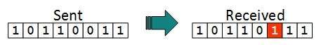
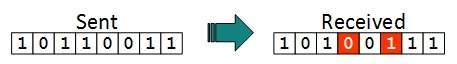
During transmission, digital signals suffer from noise that can introduce errors in the binary
bits travelling from sender to receiver. That means a 0 bit may change to 1 or a 1 bit may change to 0.
During transmission, digital signals suffer from noise that can introduce errors in the binary
bits travelling from sender to receiver. That means a 0 bit may change to 1 or a 1 bit may change to 0.
Error Detecting Codes (Implemented either at Data link layer or Transport Layer of OSI Model)
Whenever a message is transmitted, it may get scrambled by noise or data may get corrupted.
To avoid this, we use error-detecting codes which are additional data added to a given digital
message to help us detect if any error has occurred during transmission of the message.
To avoid this, we use error-detecting codes which are additional data added to a given digital
message to help us detect if any error has occurred during transmission of the message.
Basic approach used for error detection is the use of redundancy bits, where additional bits
are added to facilitate detection of errors.
are added to facilitate detection of errors.
Some popular techniques for error detection are:
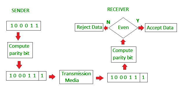
1. Simple Parity check
2. Two-dimensional Parity check
3. Checksum
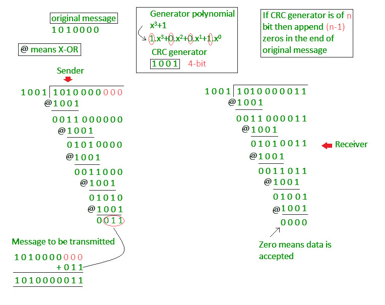
4. Cyclic redundancy check
Two-dimensional Parity check
Parity check bits are calculated for each row, which is equivalent to a simple parity check bit.
Parity check bits are also calculated for all columns, then both are sent along with the data.
At the receiving end these are compared with the parity bits calculated on the received data.
Parity check bits are also calculated for all columns, then both are sent along with the data.
At the receiving end these are compared with the parity bits calculated on the received data.